Your cart is currently empty!
Injector deadtime: theory and measurement
Background information: required fuel
An injector pulse looks something like this:
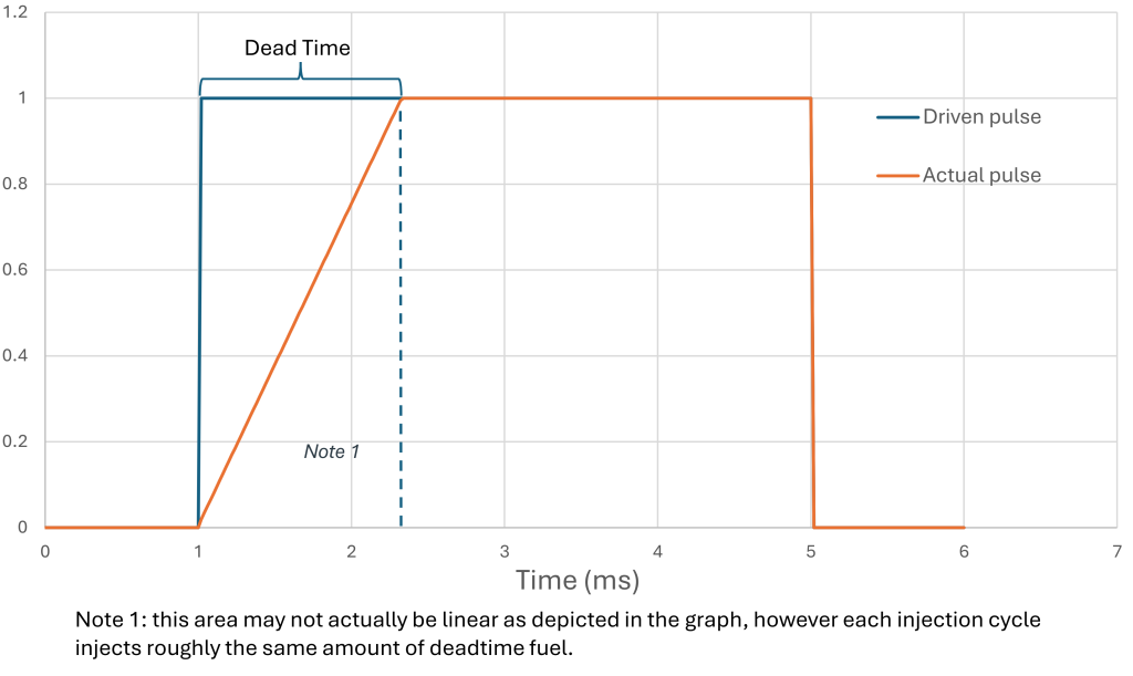
You can see the actual pulse doesn’t match the driven pulse. To compensate for that, the ECU has deadtime parameters, usually under a “injector characteristics” menu.
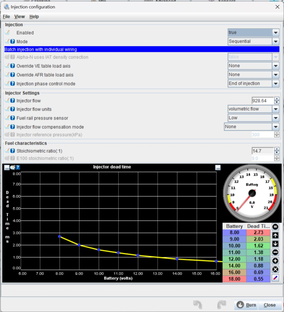
Injectors work by opening a valve against fuel pressure. As the battery voltage goes down, it takes longer for the pintle to open, as there is less force.
Usually, high quality aftermarket injectors provide that can be plugged into the tune. De-capped OEM injectors are also a popular choice, they provide the flow performance with OEM reliability and stability. However OEM injectors, along with no-name aftermarket injectors, often times don’t provide the deadtime data.
Test setup and equipment
Measuring volume accurately, more importantly consistently, can be done with a gram scale and backwards calculating using the known density of the test fluid.
An impromptu flow bench can be made by removing the fuel rail off your target vehicle, and using your ECU in “test mode”. You will need a container that won’t overload the scale, and hold about a minute of fluid (e.g. 1000cc injectors need 1L container)

You will also need a variable power supply to vary the injector voltages, at least 5 amps.
Measurement Theory
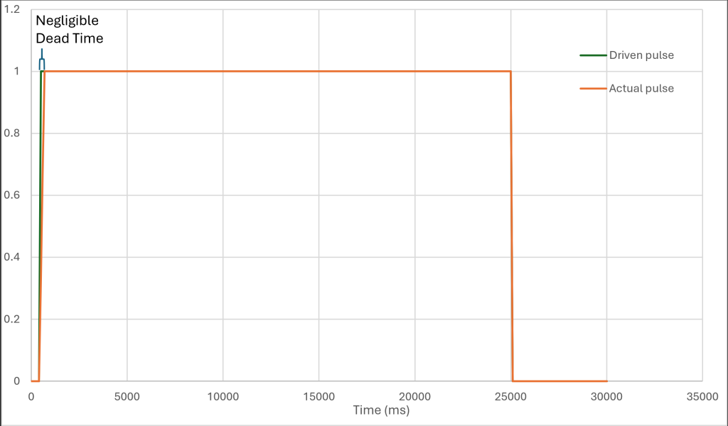
To measure deadtime we have to first find the actual flow rate. We will first find our control measurement by spraying an injector cycle for a long pulse, ideally at least 30 seconds, then measure the injected volume. This lets you find the flow rate with the error of only 1 deadtime cycle, making it negligible.
Now, we are going to spray numerous cycles that add up to the long pulse. For an example if our test pulse is 5ms and the long pulse is 30s, we would need 6000 cycles. Finding the difference between the two measurements and dividing by number of pulses reveals the volume of fuel its missing per cycle.
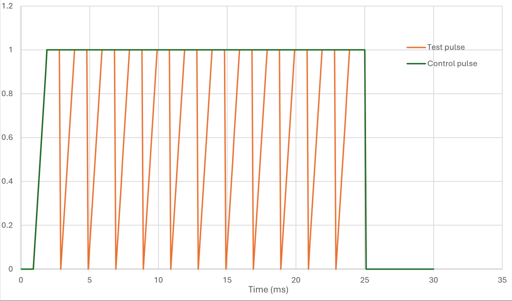
To convert volume to milliseconds, we can calculate this using the control flow measurement done earlier.
Example using a Excel sheet
Here I am flowing a set of decapped reman triton 5.4 injectors off a E350 van. These are the ones I currently have in my car as of this writing. LS1Tech forums claimed they ran 900cc at 4 bar (typical LS fuel pressure). This turned out to be true.
To begin, I adjusted the pressure on my flow bench to 4 bar, set my power supply to 12v, and filled out the g/ml of my test fluid (mineral spirits), as well as the tare of the graduated cylinder.

Next, I did a 30,000ms x 1cycle test and recorded the grams under “measured grams”. I repeated this for each of the target pulsewidths x ncycles
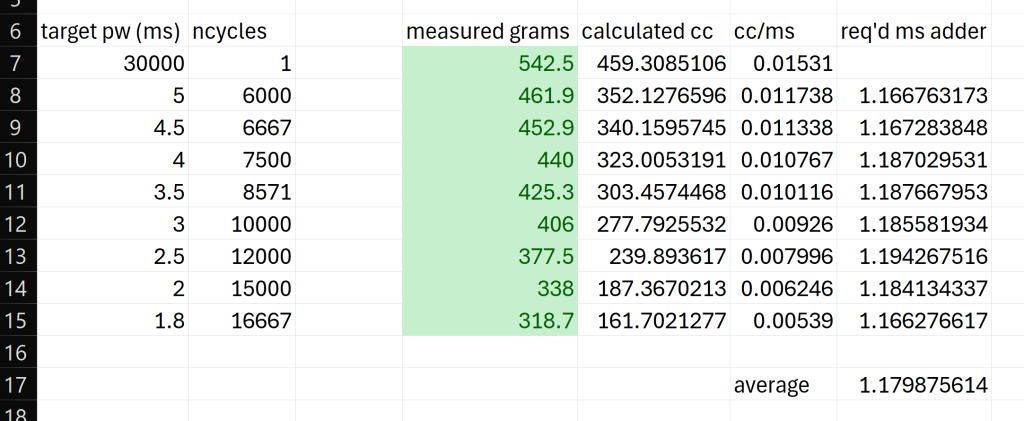
As the pulse width gets lower, the error in output volume is greater. This test is performed at multiple pulse widths, then averaged across the board.
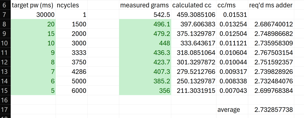
I then repeated this test across different injector voltages, on the different tabs.
Note that as the voltage becomes lower, the test uses a higher target pulse width. The test pulse width must be greater than the req’d ms adder to give valid results.
EpicECU Improvements
During the design of EpicECU, it was apparent that steady deadtimes were very important especially during cranking and startup, when the voltage varies due to lack of a alternator source. Should you decide to use a traditional injector drive over the SiD system, there is a regulated 14v output available for injector power. Even if the starter is cranking, drawing down the voltage, the injectors will see a steady voltage, hopefully allowing a more stable operation
